Figure 1: The transformer mounted in the jiffy box..
WARNING: 230-240VAC can kill. Do not attempt this project unless you have a good understanding of power and electronics. A simple mistake can result in serious injury or death. If you have any doubts at all, please consult a licensed electrician.
This is my second auto top-off project and uses a float switch as I can't accommodate a gravity fed system for the tanks in the house. Using a float switch that drives a pump I can house the reservoir in the tank stand at the same level as the sump.
I have made all the components fairly modular, to allow them to be swapped or replaced as required. The modules in the project are:
Because of the modular nature, I can change the parts around as required. For example, if the pump fails, I can just swap it for another. If I decide to change the sump, I just need new sump clips.
| Component | Cost | Place of purchase | Part number |
| Total | $75.12 | ||
| Float Switch | $38.17 | RS Components | 845-982 |
| Jiffy Box (130 x 68 x 41mm) | $3.50 | Jaycar Electronics | HB6013 |
| Terminal Strip (12 way) | $1.55 | Jaycar Electronics | HM3194 |
| Transformer (9V 150mA) | $6.95 | Jaycar Electronics | MM2017 |
| Bridge Rectifier (1.2A 400V) | $0.50 | Jaycar Electronics | ZR1304 |
| Capacitor (Electrolytic 470μF 25V) | $0.63 | Jaycar Electronics | RE6326 |
| Relay (Solid State 3-32VDC 240VAC @ 3A ) | $12.00 | Jaycar Electronics | SY4080 |
| Plug (3 pin 240VAC 10A ) | $3.65 | Jaycar Electronics | PP4000 |
| Cable (3 Core 7.5A) - 2m | $3.42 | Bunnings | |
| Socket (3 pin 250V) | $4.75 | Bunnings |
Notes about the float switch The float switch (RS 845-982) I used for this project is a change over type. It comes with three wires so that it can be used in either a normally open or normally closed operation. I did this for flexibility on my part. There is no reason you couldn't use the cheaper normally open unit (RS 331-017) and reverse the float to turn it into normally closed. The change over float switch (RS 845-982) has three wires as the switch is single pole double throw. The green wire is the common pole. The blue wire is for normally closed, i.e. when the float is down, the switch is closed and the switch opens when the float rises to the top. The red wire is for normally open and does not need to be used. Note that the float can be reversed to reverse the operations if the switch is wired incorrectly. |
The following items are also needed:
For the reservoir, I chose a 32 litre plastic container from Bunnings. It was $20.56. As this will be on a 600 litre tank, I will not put much more than 25 litres of freshwater into the reservoir in case of a failure. If 25 litres is dumped into the sump, the specific gravity will only drop from around 1.027 to just under 1.026.
To build the sump clips I used:
For the pump, I am using an old Mini-Jet MN606 I already had. This has a maximum flow rate of 600 litres per hour with no head. A slow pump is desirable as it will allow for smaller amounts of water to be added each time the float switch switches it on. The outlet takes 10 mm tubing.
In addition to the pump, 10mm tubing was required to get the water from the reservoir to the sump.
The following tools were used:
In keeping with the modular design, no soldering was required in the construction of the control unit all the components are connected using the terminal strip. (Note: the wiring on the float switch was not long enough and so I extended the length by adding another metre of wire. This required soldering.)
To start, the jiffy box was drilled for the mains input, the float switch and the 3 pin socket. The cable for the mains input required a 6.5 mm hole. The wire I used to extend the float switch wire required a 5.0 mm hole. The bolts to secure the 3 pin socket and transformer required a 5.5 mm hole and a 6.5 mm hole was required for the wires to the 3 pin socket. The hole for the wires to the socket should be offset so that the wires clear the transformer.
I cut around 12 centimetres of the 3 core cable to connect to the 3 pin socket. The outer insulation was removed and each of the three wires stripped at either end. One end of each of the wires was connected to the 3 pin socket and the other end pushed through the hole. I mounted the socket on the outside of the box and used the mounting screws to secure the transformer inside the box. See Figure 1.
![]()
Figure 1: The transformer mounted in the jiffy box..
Using a single edged razor blade, I cut and trimmed the terminal strip as shown in Figure 2. Four separate pieces of the terminal strip were required:
Those terminals which will be connected to the relay were trimmed to allow a better connection to the relay.
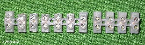
Figure 2: The terminal strip cut and trimmed as required.
The relay was connected to the terminal strips as shown in Figure 3.
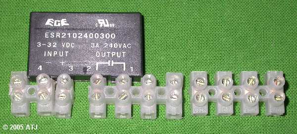
Figure 3: The terminal strips with relay connected.
Notes about the bridge and capacitor The bridge takes AC input and produces a virtual DC output. The two input leads on the bridge are marked with ~ symbols to indicate alternating current. The DC output leads are marked with a + for positive and a - for negative. The capacitor sits across the DC output to smooth the current. The capictor has its negative lead marked with a arrow along the whole length with a - symbol. The negative lead connects to the negative output from the bridge and the other lead on the capacitor connects to the positive output from the bridge. The postive leads from the bridge and capacitor connect to the positive input of the relay via the float switch. The negative leads from the bridge and capacitor connect to the negative input of the relay. |
Fine spaghetti tubing was placed over the leads of the bridge and the capacitor leaving just enough of the leads exposed to connect to the terminal strip. This is to insulate the leads. The bridge was connected to the terminal strip such that the AC input leads connect to the first two terminals, negative output to the third terminal and positive output to the fourth. The negative lead on the capacitor (the shorter lead) connects to the third terminal and the positive to the fourth. See Figure 4.
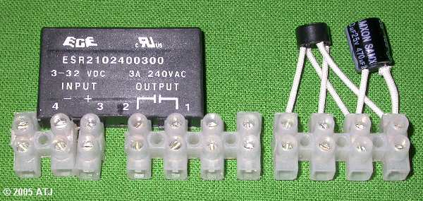
Figure 4: The terminal strips with bridge and capacitor connected.
Around 10cm of the outer insulation of the 3 core power cable (mains input) was stripped and the ends of the three individual wires stripped to expose around one centimetre of bare wire. The wire was pushed through the hole on the box. The active (brown) wire from the socket was connected to the terminal that connects to pole 2 on the relay. The active (brown) of the mains input and the active (brown) of the transformer input were connected to the terminal that connects to pole 1 on the relay. The earth (green/yellow) of the mains input along with the earth (green/yellow) from the socket were connected to the terminal to the right of the active input. The neutral (blue) for each of the mains input, transformer input and socket were connected to the next terminal to the right. This can be seen in Figure 5.
The wire from the float switch extension was pushed through the hole in the box. Some insulating tape was wrapped around the float switch wire inside the box to prevent the wire from being pulled out of the box and potentially breaking the connections. One lead from the float switch was connected to the terminal on pole 3 (positive input) on the relay. The other lead was connected to the spare terminal and this will be connected to the positive DC output. Note that it does not matter which way around the leads from the float switch are connected.
A length (around 5cm) of black hookup wire was connected to the terminal that connects to pole 4 (negative input) on the relay. See Figure 5 for this, too. The other end of this will connect to the negative DC output from the bridge. A length (around 5cm) of red hookup wire was connected to the spare terminal to which one lead from the float switched was connected. The other end of the red hookup wire will be connected to the positive DC output from the bridge.
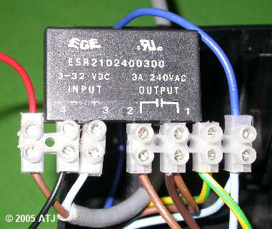
Figure 5: The terminal strips with mains input, transformer input, output to socket, float switch and hookup from DC supply connected.
The output wires (yellow) from the transformer were connected to the terminals connected to the input to the bridge. It does not matter which way around these wires are connected. The black hookup wire (that was connected to pole 4 on the relay) was connected to the terminal with the negative output from the bridge and the red hookup wire was connected to the remaining terminal (positive output from the bridge).
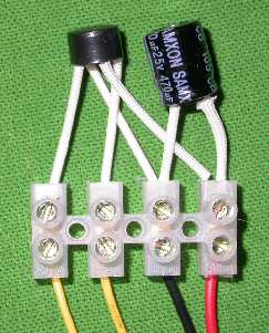
Figure 6: The terminal strips with transformer output and hook up wires to relay and float switch connected.
As the transformer has three output wires, the end of the unused (white) wire was wrapped in insulating tape.
All the wires and terminal strips were pushed into the jiffy box, being careful not to put any strain on any of the connections, and the lid screwed on.
The 3 pin plug was added to the mains input cable and the control unit was completed.
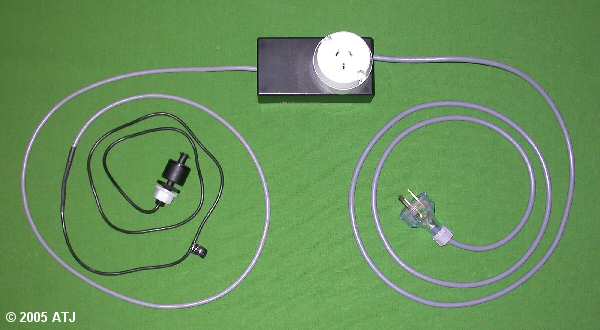
Figure 7: The completed control unit.
Two sump clips were made, one to hold the float switch and a second to hold the tubing from the pump. The clip for the float switch was made in two parts so that the height of the float switch can be adjusted, one part fits over the edge of the sump and the other includes a bracket to hold the float switch. In order to make the clip adjustable, a series of holes were required in the two pieces. The holes needed to both line up along the centre of each strip of acrylic and be equidistant from each other so that one piece raised an lowered and still have the holes line up. Two pieces of 3mm acrylic, 40mm wide and 200mm long were clamped together such that their ends were offset by around 70mm. A piece of eggcrate diffuser was also clamped to the acrylic so the corners of the holes could be used as a guide to drill the holes. Six 2.5mm holes were drilled so they could accommodate nylon bolts. It has been suggested to me that as an alternative to drilling all the holes, the two pieces could be held together with airline clamps (e.g. those green ones). This would allow for more variation in the level of the float switch.
The end (without the bolt holes) of one piece was drilled with a 12.5mm hole to accommodate the float switch. A small piece was cut out between the hole and the end to allow clearance the wire for the float switch. See Figure 9. The last 35mm of the piece of acrylic with the hole was bent at right angles. This was achieved by heating the area to be bent with a butane hand torch. See Figure 8.
The end (without the bolt holes) of the other piece of acrylic was bent so that it could fit over the edge of the sump. Again the area to be bent was heated with a butane hand torch and then bent over the edge of the sump. See Figure 8.
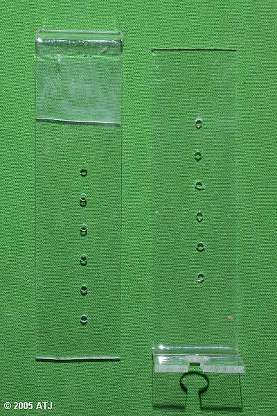

Figure 8: The completed sump clip components to hold the float switch (from in front and the side).
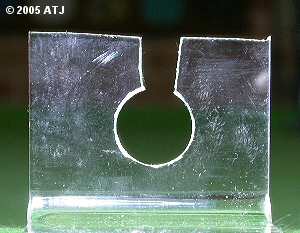
Figure 9: Close up of the part of the sump clip to which the float switch is mounted.
The clip for the tubing holder was made from a 150mm length of 3mm acrylic, 40mm wide. Four holes were drilled so that cable ties could be used to hold the fountain adapter. See Figure 10. The other end of the acrylic strip was bent over the side of the sump after heating the area to be bent with the butane hand torch. See Figure 10.
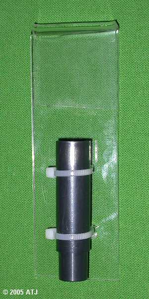
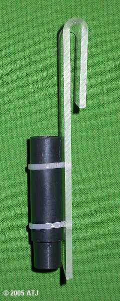
Figure 10: The completed sump clip to hold the tubing from the pump (from in front and the side).
Note that the sump clip for the water inlet to the sump was designed to ensure a large space between the bottom of the inlet and the water surface in the sump. This will prevent the water from siphoning back into the reservoir and also prevent water siphoning from the reservoir into the sump.
Initial testing was done dry. A pump was plugged into the control unit, the control unit connected to power and the float switch manipulated manually. The pump turned on whenever the float on the float switch was moved down its shaft.
The testing was repeated with the pump with tubing attached in water in one bucket . The float switch and sump clip was attached to the side of another bucket and the water level lowered by removing water. The pump turned on and pumped water into the other bucket until the water level switched the pump off.
Installation was very simple. The reservoir was placed in the stand next to the sump and the pump with tubing placed in the reservoir. Water was added to the reservoir. See Figure 11.
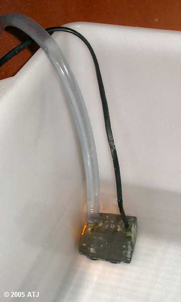
Figure 11: The float switch and sump clip in the sump.
The other end of the tubing was pushed into the fountain adaptor on the sump clip and the sump clip hung over the edge of the sump. See Figure 12. Note the clearance between the fountain adapter and the water level to prevent siphoning.
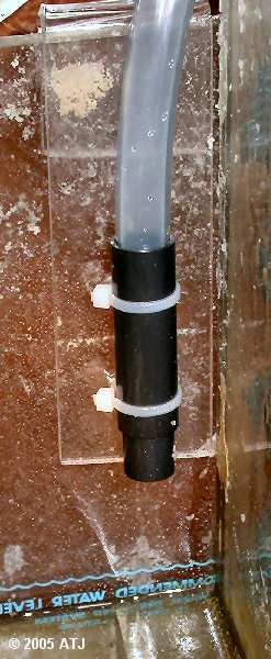
Figure 12: Sump clip with inlet tubing.
The float switch was mounted on the base of its sump clip and this was adjusted so that the float switch would be suspended at the correct height in the sump. The clip and float switch were placed in the sump. See Figure 13. Note that is important that the float switch be placed in an area of little surface movement so that the switch does not contually switch the pump on and off.
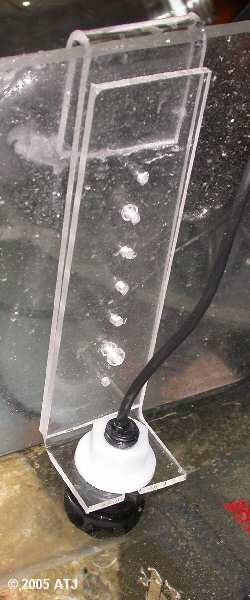
Figure 13: The float switch and sump clip in the sump.
The plug for the pump was inserted into the socket on the control unit and the power plug on the control until plugged into a wall socket and switched on. It worked perfectly.
The auto top-off system has been running on my 6' tank for a number of days now and has been working flawlessly. The water level in the sump has hardly changed where as I was having to add 2 litres of water every few days. I have also added one to 60G and 180G and these are also working well.
I am planning on using Kalkwasser in the reservoir, however, I will only do that if I replace the current pumps with peristaltic pumps which have much slower flow rates. While a failure of the float switch is unlikely, if it did fail and left the pump switched on, the amount of Kalkwasser added to the tank in a short period would raise the pH far too much. Based on What Your Grandmother Never Told You About Lime, adding just 7.5 litres of Kalkwasser in one go to a 600 litre tank would raise the pH by 0.6 to 0.7 pH units, which would be devastating.
I have been looking at a number of different peristaltic pumps but they are not cheap. Ideally, I would need one with a flow rate of around 200 mL/hr for the two 600L tanks (6' and 180G) and one with a flow rate of 50-100 mL/hr for the 200L tank (60G). If the float switch or control unit failed in the on position, a 200 mL/hr pump would only add 4.8 litres in a day which could easily be tolerated by the 600L tanks with the pH only being raised by 0.1 pH unit - if that. Similarly 100 mL/hr would result in 2.4 litres being added to 60G which is also not too much.
I have seen two units rated at 400 mL/hr. One is Prominent® duco® flex 035 and the other is SEKO PE-0.4. The former retails for around $380 which is a little too much and I'm waiting on the price for the other. A pump with a flow rate of 400 mL/hr will be a bit high, even for the 600L tanks - adding around 9.6 litres in a day in the case of a failure of the float switch. However, thanks to an idea from a fellow hobbyist, the total maximum daily flow rate could be reduced by putting the control unit on a cheap timer so that it only runs for 30 minutes every hour. Similarly, a timer set to switch on for 15 minutes every hour would reduce the maximum daily flow rate (in the event of a failure) to only 2.4 litres per day which is suitable for the 200L tank.
If I can't find an inexpensive peristaltic pump with a 50-400 mL/hr flow rate, I may buy 3 Aqua Medic SP 3000 dosing pumps which are around $200 each. These are rated at 3 L/hr but if used on a timer set to switch on for 15 minutes every 4 hours, I will have a maximum daily flow rate of 4.5 litres per day. This would also give a maximum single dump volume of 750 mL which is unlikely to raise the pH of a 600L tank by more than 0.1 pH unit. On the 200L tank, this would be around 0.4% which may raise the pH by 0.3 pH units, however, this would be in the sump and may not affect the tank too much. A timer set to switch on for 15 minutes every 8 hours will give me maximum daily flow rate of 2.25 litres per day.
Last updated: 23 December 2005